Your browser cannot save progress right now. You can still investigate; keep this tab open or enable local storage to save.
This case has been updated. Compatible choices are kept; revisit the evidence before drawing your conclusion.
01 · The briefing
Begin with the question.
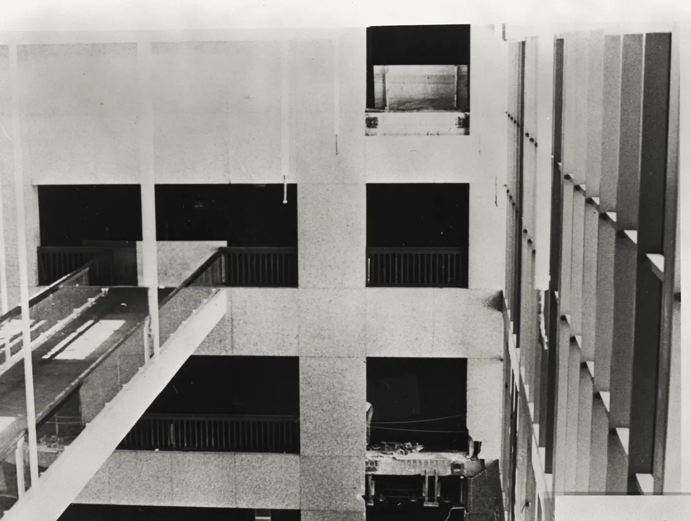
On July 17, 1981, two suspended walkways collapsed inside the Hyatt Regency hotel in Kansas City. The investigation focused on the connections between hanger rods and box beams, not simply on the amount of steel in the building. In the original arrangement, continuous rods extended past the upper walkway to support the lower one. The constructed arrangement used separate rods: the lower walkway hung from the upper walkway’s structure. That changed the route by which its weight reached the roof. Your task is to trace the load through each connection and resist an appealing oversimplification: the original detail was not adequate either. This case concerns a lethal structural failure; the investigation emphasizes mechanics and prevention rather than spectacle.
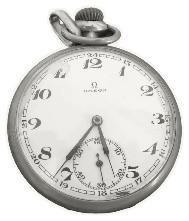
The timeline
The hanger arrangement changes from continuous rods to an interrupted arrangement during construction.
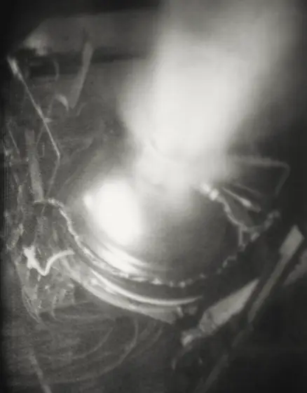
The second- and fourth-floor walkways collapse.
The National Bureau of Standards investigates the failed system.
NBS publishes its technical investigation.
NBS announces findings on inadequate connections and the changed load path.
A researched reconstruction for learning. These reasoning steps simplify a complex record; no score can capture the full history.
02 · The evidence
What does the record show?
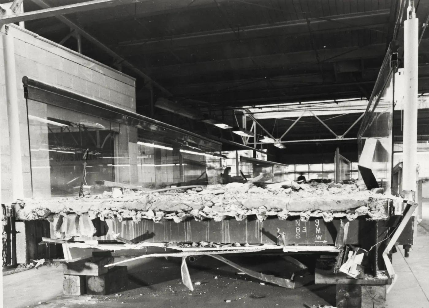
Read each exhibit before settling on an explanation. The numbered source links below every exhibit lead to the record behind it.
Original load path
With a continuous rod, the lower walkway’s load travels in the rod past the upper walkway rather than first being transferred through the upper box-beam connection.
Source record [s1]
Changed load path
With separate rods, the upper walkway connection must transfer the load of both levels. The report describes this as essentially doubling its demand.
Source record [s1]
A local failure
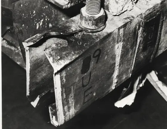
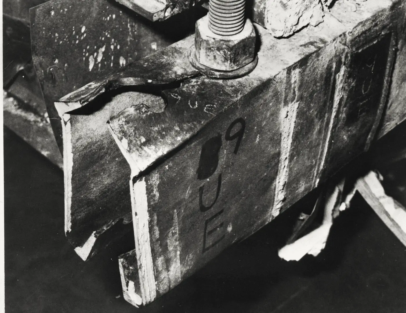
NBS located initiation at a box-beam/hanger-rod connection of the fourth-floor walkway.
Source record [s1]
Not an adequate original
The original connection design also fell short of the applicable code requirements. Reversing the change alone is not a complete safety argument.
Source record [s1]
03 · Your reasoning
Follow the strongest explanation.
Choose an interpretation, then compare it with the evidence. You can revise your choice. The goal is understanding, not a perfect score.
04 · The findings
The chain behind the outcome.
The collapse illustrates the difference between geometric similarity and structural equivalence. Separate hanger rods made fabrication different, but they also changed which connection had to transfer the lower walkway’s weight. The fourth-floor box-beam connections were consequently asked to carry substantially more load. NBS also found the original connection design inadequate, so the responsible conclusion is not that an otherwise safe design was ruined by one small substitution. The load path and the available resistance both needed checking. In the simplified example used here, W and 2W explain the mechanism; they are not claimed measurements of the actual loads that evening. For a real design, connection geometry, material behavior, load combinations and code requirements must all be evaluated. The transferable lesson is to treat a fabrication change as a possible change to the engineering model, with explicit review of every affected connection.
Take the method with you
- Follow force through connections, not just through visible members.
- A fabrication change can alter the structural model.
- An inadequate original design is not a safe fallback.
You can read findings at any time. Exploring every reasoning step marks this case as complete in your notebook.
The open record
Sources & further reading
Read the original record and its scope before relying on a conclusion. Source references support the exhibit summaries; Faultory’s reasoning prompts are editorial reconstructions.
- s1
- s2NIST — Official report record
www.nist.gov
Written and curated for Faultory by Yunus Emre Vurgun, with AI-assisted research and drafting. Sources and interpretations can need correction. Read our editorial standards or report an issue.
Keep investigating